Bending and denting: Parts for steel bridges under pressure

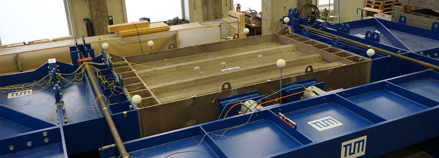
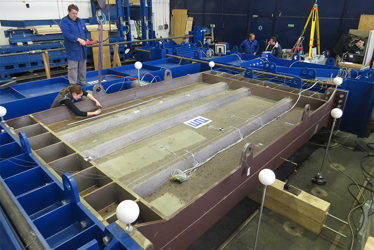
50-Tonnen-Prüfstand für Brückenbauteile aus Stahl (Foto: Lehrstuhl für Metallbau, TUM)
In the coming years, more than 2000 bridges in Germany will need to be renovated or replaced by new ones, with the costs running into billions. Many of the new bridges will be steel bridges, which are often more durable and easier to inspect and repair than reinforced concrete bridges. "Given the enormous construction costs of the steel bridges, it pays to exploit potential savings – for example, by optimising the use of materials", explains Martin Mensinger, holder of the Chair of Metal Construction at the TUM.
Up to now, the basis for the static calculation of steel structures has been the Eurocode 3 standard (DIN EN 1993-1-5). However, the regulations contained therein for complex loads have been the subject of controversial discussion for years, and scientific validation is necessary to further develop the standard. At the moment, architects are forced to calculate using a procedure that was only developed for non-reinforced components, which in practice leads to bridge components often being oversized, explains Nadine Maier, who is responsible for the planning and execution of the tests on the test rig. In order to make bridges as light as possible and as stable as required, however, it is necessary to know to a very precise degree the forces that the components are able to withstand. However, up until now it has been difficult to determine the load limits in the laboratory: The components of a steel bridge are several metres long and weigh several tonnes, so that scientists often reach technical limits.
On the construction site, the bridge components, each segment being several metres long, are welded and continuously pushed forward into the open space. Until the structure reaches the next bridge pillar, the entire load is on the segment above the last pillar, at which point in time the load is as high as it can be. After completion of the bridge, the forces acting on the components are very much lower. The team at the TUM has now developed the huge test rig on behalf of the North Bavaria Motorway Directorate. Using it, reinforced bridge components with real dimensions can be stressed simultaneously in two directions. The same forces are applied that occur during the construction of a steel bridge.
The test rig, a colossus weighing 50 tonnes that fills an entire laboratory space, can simulate these maximum forces that occur during construction. The test rig is designed as a modular U-frame with external dimensions of 8mx12m, with the 3mx4m-large test pieces installed on its longitudinal side. From a physical point of view, two forces act simultaneously here: The components are compressed both in the longitudinal direction and perpendicularly. Engineers term this bi-axial pressure load. The 12 square-metre-large bridge sections to be tested are pressed with the aid of hydraulic presses until the steel yields and – following a clearly-audible crack – is dented.
Actual testing of the components for the new motorway bridge near Oberthulba between Würzburg and Fulda was carried out in winter 2017/2018. Six differently-dimensioned side components for the planned bridge were dented in the interest of science. "With the help of the results, the structural engineers can now plan more precisely and dimension the components in such a way that they can withstand the extreme conditions during the construction phase and at the same time optimise the use of materials", explains Nadine Maier. Further trials are planned for winter 2018/2019. The test items in this case will be produced on an almost 1:1 scale in order to detect imperfections that arise during the production process.

